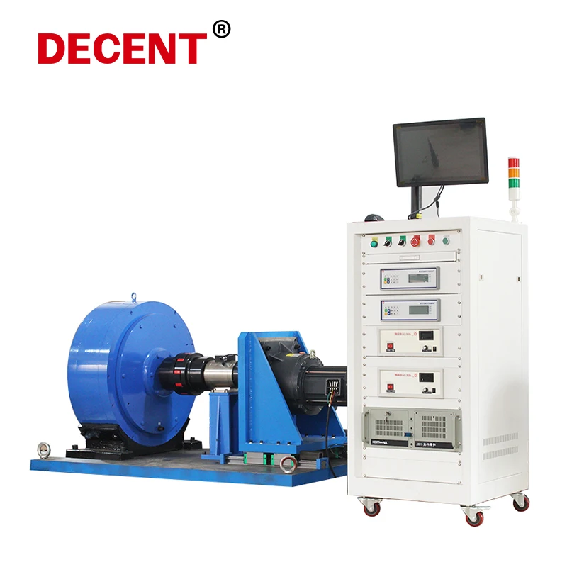
One:Brake (simulated load)
1. Magnetic powder brake 2. Hysteresis brake 3. Eddy current brake
Two:The motor power supply
Three:Electrical parameter table
Electrical parameter table, used to collect the input to the motor under test current, voltage, power, frequency, and other parameters, accuracy of 3 ‰
Four:Coupling
1. Coupling overview 2. Couplings are included with the goods
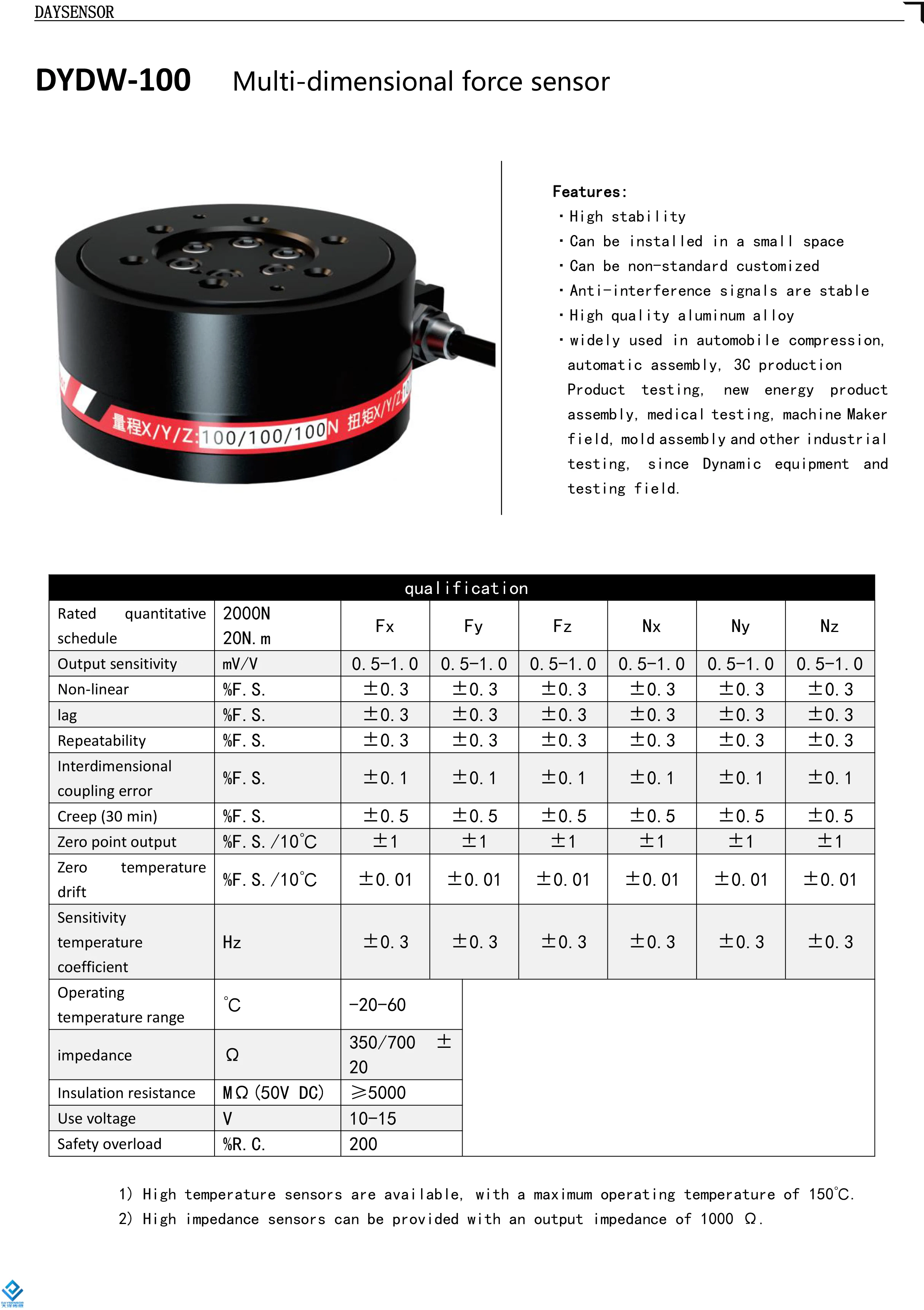
Five, dynamic torque sensor
Six. Motor fixture under test,Two dimensional adjustable motor fixture,Three dimensional adjustable fixture,Quick-clip motor bracket,L-type motor support,Custom motor bracket
Seven. Test cabinet control cabinet
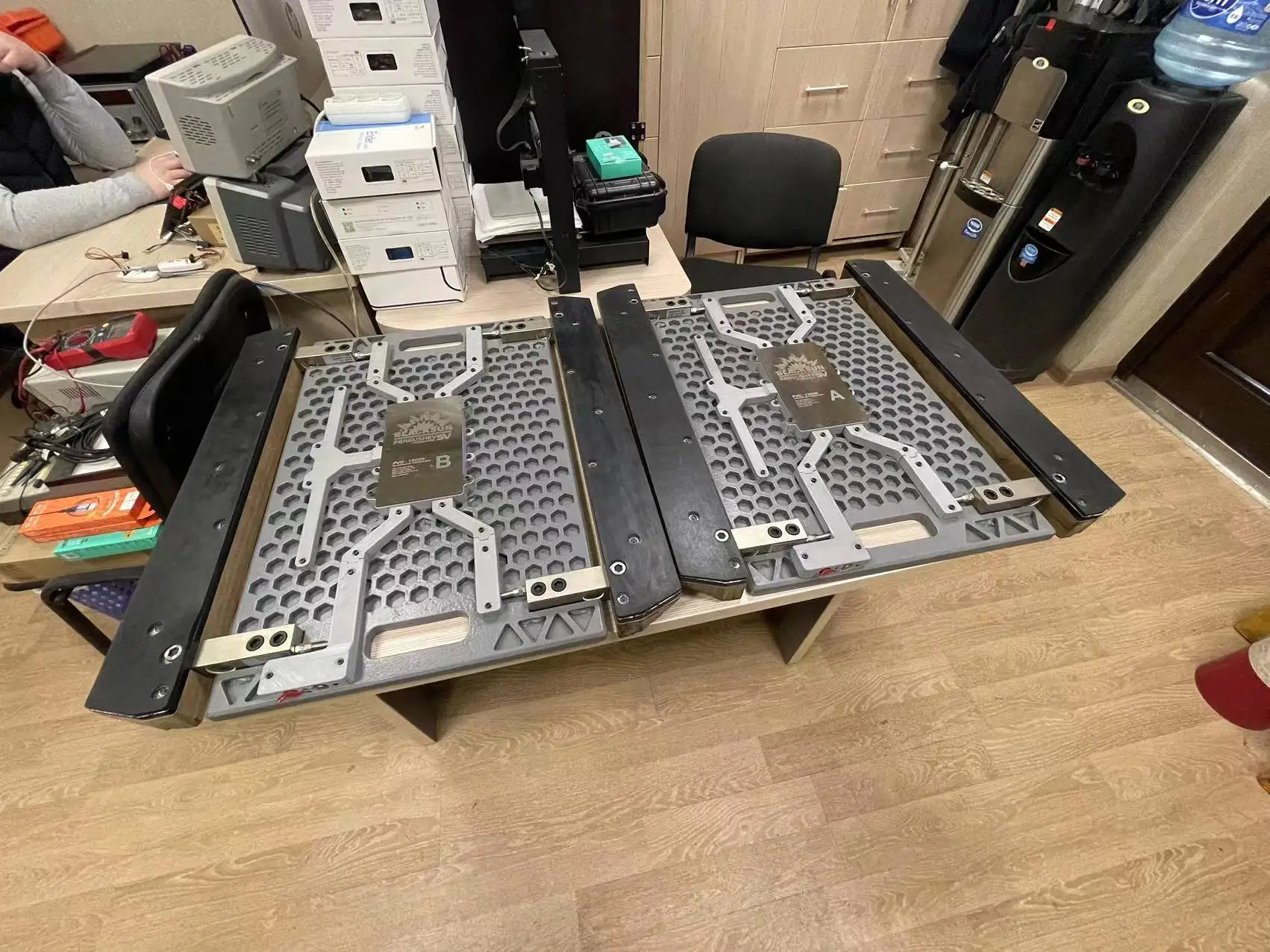
Eight, bottom plate
Nine. Software
1·Still torque can be measured, with the rotational torque ·Display the current measured torque value and the speed value in real time
2·The current power value can be calculated directly
3·Support RS485 communication and support active upload protocol ·Communication rates are up to 500 or 1,000 times per second
4·This sensor supports the simultaneous output of the transmission current and the transmission voltage
5·The sensor comes with a OLED display with a resolution of 128 * 64
6·Simple calibration, zero clearance, and filtering can be performed
7·Allow a sensor overload of 200%
8·Above 1 / 1000 accuracy, excellent zero-point stability

Technical characteristics
a. Comprehensive accuracy over 0.1% and nonlinearity over 0.02%
b. Sampling speed 3200 / s
c. Analog input signal range-15~15mV
d. Display scale 999999 or 99.999
e. Bridge supply voltage: 5V/100mA, proportional collection
f. Temperature drift is less than 20ppm
g. Transmission Output 0~10 or-5~5V and 4-20mA
h. Power supply voltage: 12~30V DC, <5W
i. -20~70 ℃ Relative humidity <90% (no dew)
1. Power supply: connect 24V-and 24V + according to the figure shown
2. Common acquisition signal line: SG + and SG-access sensor signal line are green, white, EX + and EX-access sensor power supply red and black
3. High-speed acquisition signal line: SG1 + and SG1-access sensor signal line are green, white, EX1 + and
EX1-access sensor power supply red and black
4. 485 Communication interface: T\R terminal from USB to 485 respectively
5. Customizable CAN communication interface: CANL and CANH ports of corresponding CAN devices
6. Customizable high-speed magnetic dual output: HO1 access to motor direction control end, HO2 access motor speed
control end, GD access motor power negative
7. Four ordinary output: OUT1, OUT2, OUT3, OUT4 corresponding to instrument four switch output (output OUT3
and OUT4 are common with input, as output no internal surge protection, so try not perceptual load, or perceptual
load must connect the external flow diode. )
8. Double common input: IN1, IN2 input for corresponding instrument